Reset is part of the design
Reset puts a circuit into a known starting state. It can clear a state machine, mark buffered data as invalid, or stop an interface from accepting traffic until initialization is complete.
With several clock domains, one reset wire is not the whole solution. Each domain has its own clock edges, and the moment reset is released matters. I separate two questions: how quickly must the circuit enter reset, and how should it leave reset?
This article uses an active-high reset: 1 means reset is asserted, and 0 means it is released. An active-low design follows the same reasoning with the polarity reversed.
Asynchronous assertion: enter reset without waiting
Asynchronous assertion means a register can enter its reset state without waiting for a clock edge. That is useful when reset must work even while a local clock is stopped or has not started.
“Asynchronous” does not mean zero physical delay. The reset still travels through real wiring and must satisfy the device’s minimum pulse-width and electrical requirements. A narrow glitch is not a reliable reset request, and a mechanical pushbutton may need conditioning or debouncing.
Whether asynchronous assertion is necessary depends on the system. A fully synchronous local reset can be a good choice when the clock is running and the reset request is handled correctly. I do not assume every register in an FPGA needs an asynchronous reset.
Why asynchronous release is the difficult part
When an asynchronous reset is removed close to an active clock edge, it can violate the receiving register’s recovery or removal requirements. These describe when an asynchronous control may safely become inactive around a clock edge.
The result can be metastability or inconsistent startup behavior. Different registers may not begin operating together as intended, especially when reset routing and clock arrival times differ. A state machine can therefore start incorrectly even though an ideal RTL simulation looks fine.
The usual pattern for an asynchronous reset request is asynchronous assertion, synchronous release. Assert the local reset without waiting for a clock, then release it through a synchronizer driven by the local clock. Synchronization reduces the probability of metastability propagating; physical implementation and timing checks still matter.
Give each clock domain its own reset synchronizer
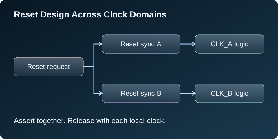
If CLK_A and CLK_B are unrelated, a reset synchronized to CLK_A is still asynchronous to CLK_B. I use a separate reset synchronizer for each destination domain instead of distributing one domain’s synchronized reset everywhere.
Both synchronizers can receive the same external request. Each releases its output according to its own clock. That means the two domains can leave reset at different times, which is normal.
Within one domain, I normally use a common local reset for logic that must restart together. Creating independent synchronizers for tightly related blocks in the same domain can introduce different release cycles. Separate reset groups are possible, but their interaction needs an explicit design.
A small VHDL reset synchronizer
The example below uses three stages. When arst is high, all stages become 1 asynchronously. After the request goes low, zeros move through the stages on rising edges. The final stage supplies the local reset.
library ieee;
use ieee.std_logic_1164.all;

entity reset_sync is
  generic (STAGES : positive := 3);
  port (clk : in std_logic;
        arst : in std_logic;
        rst_local : out std_logic);
end entity;

architecture rtl of reset_sync is
  signal reset_pipe : std_logic_vector(STAGES - 1 downto 0);
  attribute ASYNC_REG : string;
  attribute ASYNC_REG of reset_pipe : signal is "TRUE";
begin
  assert STAGES >= 2
    report "Use at least two reset synchronizer stages"
    severity failure;

  process (clk, arst)
  begin
    if arst = '1' then
      reset_pipe <= (others => '1');
    elsif rising_edge(clk) then
      reset_pipe <= reset_pipe(STAGES - 2 downto 0) & '0';
    end if;
  end process;
  rst_local <= reset_pipe(STAGES - 1);
end architecture;
The ASYNC_REG attribute tells Vivado that these registers form a synchronizer. It helps the implementation flow recognize the structure; it does not replace clock constraints, reset timing analysis, or review of the implemented circuit. Other vendors have their own attributes and guidance.
Three stages are an example, not a universal reliability choice. The required depth depends on the device, clock frequency, reliability target, and implementation. For an AMD production design, I would consider the supported XPM_CDC_ASYNC_RST macro, using the library documentation for the actual target family.
Only the final stage drives application logic. I do not use the intermediate stages as additional resets or enable signals.
What happens after the reset request goes low?
In the accompanying RTL test, CLK_A has a 10 ns period and CLK_B has a 14 ns period. The shared request goes low at 12 ns.
- Domain A sees rising edges at 15, 25, and 35 ns. Its three-stage local reset goes low just after the 35 ns edge in the RTL model.
- Domain B sees rising edges at 21, 35, and 49 ns. Its local reset goes low just after the 49 ns edge.
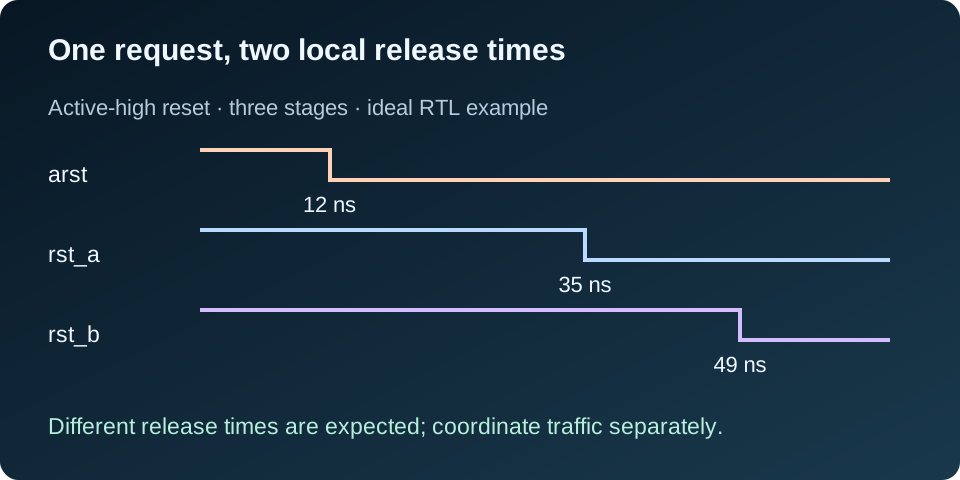
Application registers triggered by the same edge still see reset asserted on the edge that releases the synchronizer output. In this example, they normally begin work on their following rising edge. Physical reset distribution must still meet the receiving registers’ timing requirements.
If a domain’s clock remains stopped, its local reset stays asserted after the external request is removed. It can release only once enough valid clock edges occur. Startup control must ensure the clock can start without depending on logic that is still held in reset.
Use the local reset deliberately
For logic that needs asynchronous assertion, a local register process can use the synchronized reset like this:
process (clk_a, rst_a)
begin
  if rst_a = '1' then
    valid_a <= '0';
  elsif rising_edge(clk_a) then
    valid_a <= next_valid_a;
  end if;
end process;
This is an integration fragment: valid_a and next_valid_a belong to the surrounding design. A process with a synchronous reset inside rising_edge would have different assertion behavior and would require clock edges to reset its registers.
I reset the state that must be known, such as control state, valid flags, and counters needed for startup. Resetting every data register can increase routing load and prevent efficient use of memories or DSP resources. A datapath can often remain unreset if its output is ignored until valid data arrives, provided that behavior is designed and verified.
Coordinate startup before sending data
A released reset does not mean that a domain is ready to communicate. A memory controller, codec, or other interface may still be initializing. If one producer starts sending before its consumer is ready, the first transaction can be lost.
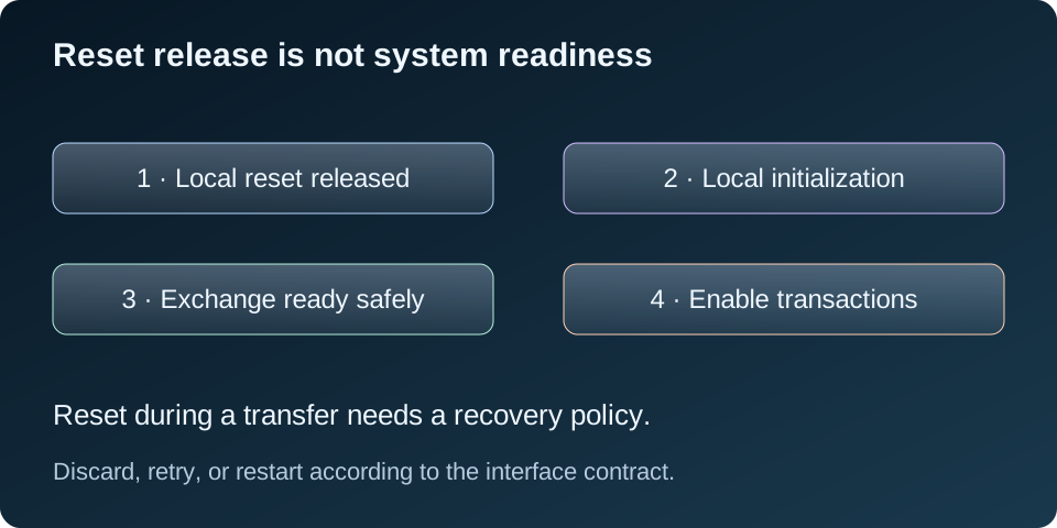
I define when each domain becomes ready, transfer that information through a suitable CDC protocol, and enable traffic only when the interface’s startup conditions are met. A readiness signal is not a reason to combine asynchronous wires directly.
Reset during a transaction also needs a policy: discard pending work, retry it, or restart the interface. Resetting one side of an asynchronous FIFO or handshake while the other continues can invalidate their shared protocol state. I follow the IP’s reset requirements and verify partial-reset behavior explicitly.
What I check in simulation and implementation
- Assert reset between clock edges and confirm the local reset outputs assert without a clock edge.
- Release at several phases relative to each clock and check that each local reset follows its own release sequence.
- Stop a local clock, remove the request, and check that the domain remains in reset until its clock resumes.
- Reassert reset during activity and verify the defined transaction recovery behavior.
- Check that valid outputs stay inactive until initialization and readiness conditions are satisfied.
- Review synchronizer recognition, placement, reset pulse width, reset distribution, and recovery/removal timing using the device-specific flow.
I do not blanket-cut every reset-related path just to silence timing reports. Any exceptions must follow the synchronizer or IP guidance and preserve the checks required for the local reset’s distribution. For broader context, AMD discusses reset tradeoffs in its reset methodology guidance.
The downloadable testbench checks basic two-domain assertion, release, and restart behavior. It passed seven functional checks at 92 ns in GHDL. It does not cover the complete checklist above and does not simulate analog metastability or prove physical reset safety.
ghdl -a --std=08 reset_sync.vhd tb_reset_sync.vhd
ghdl -e --std=08 tb_reset_sync
ghdl -r --std=08 tb_reset_sync --assert-level=error
My starting rule is straightforward: enter reset as the system requires, release it with each local clock, and coordinate readiness before exchanging data. Reset deserves the same design attention as the datapath it controls.