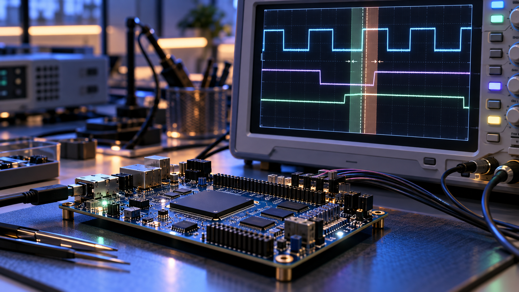
What setup and hold actually mean
A design can behave correctly in RTL simulation and still fail timing after implementation. RTL describes what the circuit should do. Timing analysis checks whether the implemented circuit can do it within the available time.
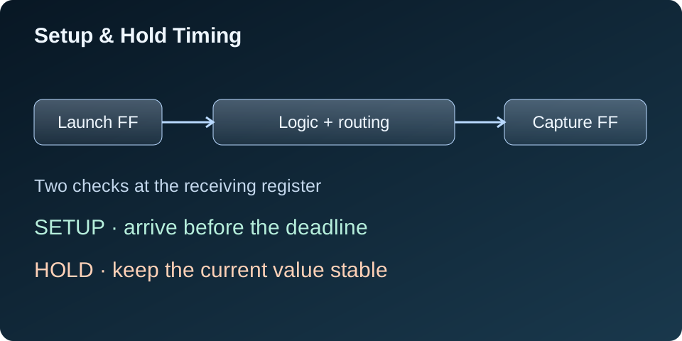
I find it easiest to start with two registers. The first launches data, the logic processes it, and the second captures the result. Data takes time to leave the first register, pass through logic, and travel along the routing.
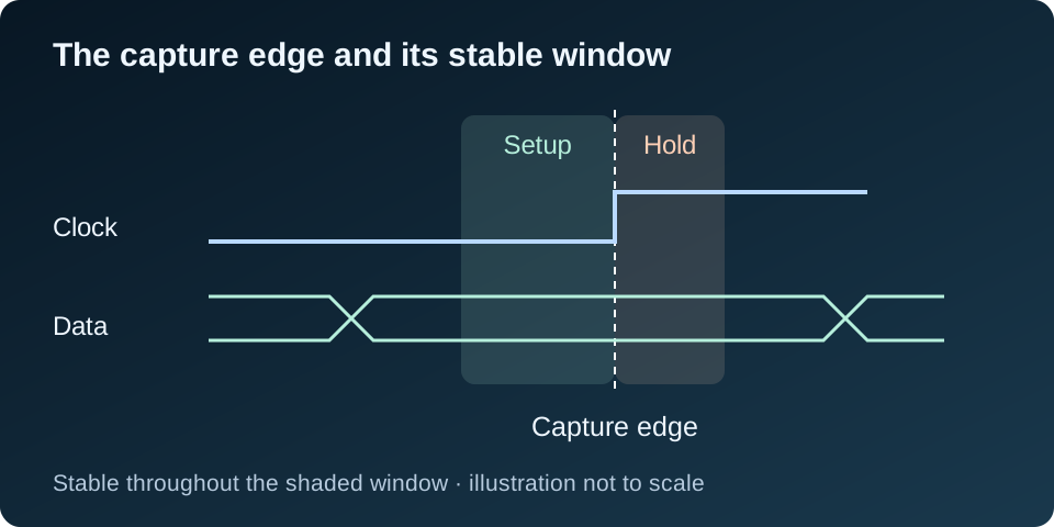
Setup time is how long the data must be stable before the receiving clock edge. Hold time is how long it must remain stable after that edge. These are requirements of the receiving register, rather than delays that I choose in VHDL.
Setup: has the result arrived in time?
Consider two registers on the same rising-edge clock, with a 10 ns period, or 100 MHz. Data launched on one edge is normally captured on the next. The usable logic budget is less than 10 ns because clock-to-Q delay, setup time, clock uncertainty, and the clock-path relationship also matter.
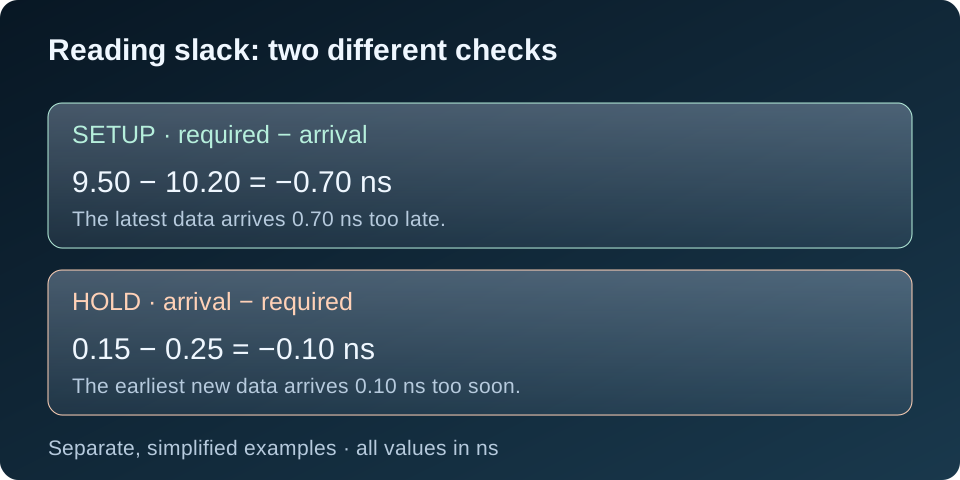
In a simplified example, the tool calculates a required arrival time of 9.50 ns. The latest data arrives at 10.20 ns. Setup slack is 9.50 − 10.20 = −0.70 ns. That path misses its deadline by 0.70 ns.
For setup, slack = required time − arrival time. Positive slack means the analyzed path meets its requirement; negative slack means it fails. I use the tool’s calculated times rather than subtracting logic delay from the clock period and assuming that is the full answer.
Hold: does the old value stay long enough?
Hold checks the opposite end of the problem: new data must not reach the receiving register too soon and disturb the value it is capturing. For a simple same-clock path, this usually concerns the same nominal clock edge rather than the next period.
Suppose the earliest new data arrives at 0.15 ns, but it must not arrive before 0.25 ns. Hold slack is 0.15 − 0.25 = −0.10 ns. The new data is 0.10 ns too early.
For hold, slack = arrival time − required time. A higher clock period generally does not solve this same-edge check. Clock skew matters too: a later capture clock can help setup while making hold more difficult.
How I read a timing report
I first check that the clocks and constraints describe the intended hardware. An incorrect clock period, missing generated clock, or missing I/O delay can make a report misleading. A path that is not constrained is not evidence that timing has passed.
Then I read a failing path in this order:
- Check type: setup uses maximum-delay analysis; hold uses minimum-delay analysis.
- Startpoint and endpoint: identify the launching and receiving registers, or the relevant I/O ports.
- Launch and capture clocks: check their periods, selected edges, and relationship.
- Requirement and slack: understand the deadline and the size of the failure.
- Path details: separate cell delay from routing delay and inspect logic depth, fanout, and clock skew.
Illustrative setup path — simplified, not a Vivado export
Startpoint:       input_reg/Q
Endpoint:         result_reg/D
Launch / capture: clk / clk
Clock period:     10.00 ns
Required time:     9.50 ns
Arrival time:     10.20 ns
Slack:            -0.70 ns  (FAIL)
A long chain of arithmetic and selection logic points toward a different fix than a short logic path with excessive routing. I also check whether the same structure appears in many failing paths.
In the summary, WNS is the worst setup slack and TNS accumulates negative setup slack across failing endpoints. WHS and THS describe the corresponding hold results. I check setup, hold, clock coverage, and relevant pulse-width checks together. A good WNS alone is not a complete timing sign-off.
When adding a pipeline stage helps
If a setup path contains too much combinational work in one cycle, I consider dividing that work with a register. For example, decoding, arithmetic, and result selection may be split into two stages. Each stage then has its own register-to-register timing budget.
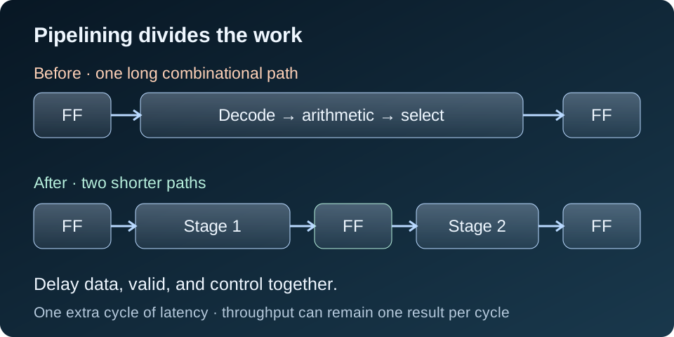
The tradeoff is latency. This example adds one cycle before the result becomes available. For independent inputs, the pipeline can still accept one new input per cycle once it is running. Feedback loops, dependencies, or handshakes may limit that throughput.
I also delay the matching valid flag, channel identifier, and control signals. In a video pipeline, adding a register to pixel data without aligning its timing signals can produce a functional error even when the timing report passes. The testbench must account for the new latency and check that each result still belongs to the correct input.
When the architecture needs attention
Adding a register is useful only if it addresses the actual bottleneck and the application allows the extra latency. I look more closely at the architecture when:
- One operation dominates: use suitable DSP or memory resources and their supported internal pipeline registers, or restructure the operation.
- A large mux dominates: consider a hierarchical selection structure or divide the work across stages.
- Routing dominates: inspect congestion, physical distance, resource placement, and high-fanout control signals. Adding logic stages alone may leave the routing problem.
- A recurrence cannot accept another cycle: consider a different algorithm, parallel processing, or a slower multi-cycle implementation with an explicit protocol.
If the system specification allows a lower operating frequency, a longer period can give setup more time. That is a performance decision, and it does not generally fix hold. I do not add a false-path or multicycle exception simply to remove a violation. An exception must describe actual circuit behavior; multicycle paths also require careful review of the associated hold relationship.
How I approach a hold violation
A hold failure is not a reason to add arbitrary combinational logic in RTL. Synthesis may remove that logic, and its delay is not a reliable physical guarantee. Adding a pipeline stage is also not a general hold repair.
I check the clock relationship, generated-clock definitions, I/O constraints where applicable, and any exceptions first. With valid constraints, the implementation tools can repair many internal hold paths through physical delay and routing adjustments. For source-synchronous interfaces, device-specific input or output delay resources may be part of the interface design.
If hold still fails after routing, I inspect the exact data and clock paths and the implementation messages. Any repair must be checked against setup again, because extra data-path delay consumes setup margin.
My practical timing-closure workflow
- Define clocks, generated clocks, I/O timing, and justified exceptions.
- Check constraint coverage and clock-domain crossings.
- Use synthesis timing to identify likely structural problems early.
- Inspect implemented paths and choose a fix based on logic, routing, or clock behavior.
- Verify the functional consequences, especially pipeline latency and control alignment.
- Reimplement and check final routed setup, hold, and other applicable timing checks across the required analysis corners.
Static timing analysis checks timing under the supplied constraints and device models. Functional simulation checks behavior. I need both: a circuit can be logically correct but too slow, or meet timing while implementing the wrong behavior.
My main rule is simple: setup asks whether data arrives early enough; hold asks whether new data arrives too early. Once I know which check is failing and what dominates the path, the next design decision becomes much clearer.
Further reading
For the detailed tool definitions and timing-closure guidance, I refer to AMD’s Vivado Design Analysis and Closure Techniques guide (UG906). Its hold relationship explanation covers the arrival/required-time equations, and its minimum-delay analysis guidance explains why setup and hold need analysis across the relevant corners.