One filter, two hardware design approaches
My HDMI image-processing project already includes a VHDL Sobel filter. I have also written an HLS version, giving me a useful case study: how do two descriptions of the same neighborhood operation change the way I design and verify the hardware?
Sobel highlights changes in image intensity. On the yellow car below, the body outline, windows, wheels, and surrounding objects help explain the effect. It is a useful building block for image analysis, though edges alone do not identify a car or distinguish an object from its background.
The same car, before and after Sobel
Original scene
Color and intensity information before edge extraction.
Sobel edge illustration
Contours illustrate the response to local intensity changes.
These are the existing conceptual car illustrations from my image-processing project. They are not outputs measured from either Sobel implementation and do not establish numerical equivalence.
Streaming the neighborhood
Both versions consume 8-bit grayscale pixels and carry data-enable, horizontal-sync, and vertical-sync signals. Grayscale conversion belongs upstream. Two previous image lines and a small sliding window provide the 3 × 3 neighborhood; a full-frame buffer is not inherently required for this local operation.
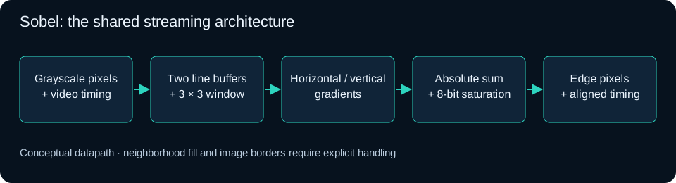
Horizontal and vertical gradients estimate intensity changes in two directions. These implementations use the sum of their absolute values and saturate the result to eight bits. That avoids a square-root magnitude calculation, but it is an approximation to Euclidean gradient magnitude. Border handling and the initial neighborhood fill remain part of the filter’s specification.
With the default 1,920-pixel line capacity, the two 8-bit line histories contain 30,720 bits of pixel storage before window registers and memory-mapping overhead. Both descriptions need that history; HLS does not remove the underlying storage requirement.
Where VHDL helps
VHDL gives me direct control over the registered memory reads, window movement, gradient arithmetic, and output stages. I can inspect the pipeline cycle by cycle and deliberately delay video timing alongside its corresponding pixels. This is especially useful when inserting a filter into an existing fixed-rate HDMI path.
It also makes arithmetic widths, reset behavior, and resource choices explicit. For a compact, stable filter with demanding integration requirements, that control can be worth the additional design effort. VHDL still needs synthesis and routed timing checks: writing registers explicitly does not guarantee a smaller or faster result.
What changes in my HLS version?
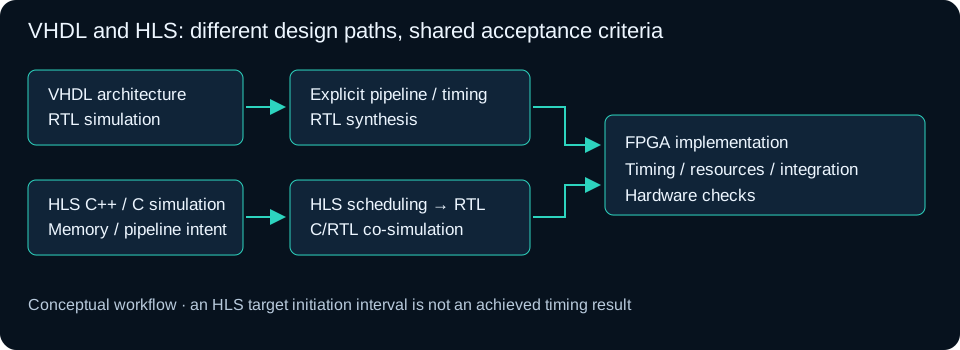
The HLS version expresses the neighborhood update and gradient calculation in C++, with fixed-width pixel types. Its design intent includes two block-RAM line buffers, a fully partitioned small window, and a pipeline target initiation interval of one. It uses plain pixel and video-timing ports with a free-running control interface; this particular module is not an AXI4-Stream accelerator.
HLS schedules operations and generates RTL from that description. The initiation interval is the spacing between successive pipeline starts, rather than the time taken for one pixel to reach the output. A requested interval of one expresses the intended throughput; achieved scheduling, latency, memory access behavior, and timing must come from successful reports. AMD explains this distinction in its HLS pipeline documentation.
Plain timing ports make integration familiar, but they do not make timing alignment automatic. The generated RTL must be checked for pixel/control latency, reset behavior, and the absence of an upstream backpressure mechanism in this fixed-rate interface.
Choosing for this use case
| Decision | VHDL advantage | HLS advantage |
|---|---|---|
| Pipeline control | Explicit register boundaries and timing paths. | Compiler scheduling guided by clock and pipeline constraints. |
| Algorithm changes | Precise control over each revised datapath. | Potentially faster iteration on arithmetic and related kernels. |
| Verification | Direct visibility into cycle-level RTL behavior. | C-level reference comparisons before RTL co-simulation. |
| Memory architecture | Explicit access timing and inference structure. | Storage binding and array organization express implementation intent. |
| Integration | Fits custom video timing and control naturally. | Can generate reusable IP, with interface and latency review. |
| Final performance | Neither wins by language alone. Compare equivalent designs after synthesis and implementation. | |
Where HLS could be favourable
I would favour HLS when the work involves repeated algorithm changes: exploring derivative filters, changing arithmetic precision, evaluating different neighborhood operations, or assembling several image-processing stages. C-level tests can make those iterations easier to express and compare before investing in a detailed RTL pipeline. The benefit depends on maintaining a reusable testbench and a hardware-aware memory architecture.
HLS can also suit a team with existing C++ image-processing models, or a family of related accelerators where IP reuse matters more than hand-tuning every register. Larger kernels and multi-stage pipelines may offer more opportunity to explore parallelism, but they also increase buffering and bandwidth demands. Existing C++ does not become efficient hardware simply by compiling it.
For this small 3 × 3 Sobel operation, the arithmetic is already simple. The strongest HLS argument is development flexibility and reuse, rather than an assumed speed or area improvement. If I need exact cycle-level behavior in a mature HDMI pipeline, VHDL remains a strong choice. A mixed system is also practical: HLS for selected processing kernels, VHDL for video transport, timing, and system control.
What must be demonstrated before comparing results?
First, both versions need the same input images, border policy, saturation behavior, frame transitions, and output-coordinate convention. A constant image, horizontal and vertical edges, impulse patterns, and randomized frames help expose mistakes. Comparing pixels requires accounting for pipeline latency and the position of the center pixel within each causal 3 × 3 window.
My HLS testbench includes constant, directional-edge, impulse, checkerboard, ramp, and random patterns, plus line-capacity and frame-change cases. The saved C-simulation logs inspected for this article end in a linker failure. They do not establish a passing run. No successful HLS synthesis, co-simulation, routed implementation, or physical-board result is claimed here.
The next evidence should include passing C simulation, C/RTL co-simulation, an achieved initiation interval and latency, resource reports, and routed timing for the same device and clock constraints. The HLS build script defaults to the XC7Z010 and a 10 ns target clock; that target is a constraint, not a measured operating frequency. Finally, the complete video path must be checked on hardware.
That comparison will show where HLS saves development effort and what tradeoffs the generated hardware introduces. Until then, this is an architecture case study, not a benchmark declaring one implementation the winner.
Further reading
AMD Vitis HLS User Guide explains scheduling, interfaces, synthesis, and verification. My implementation is prepared for Vitis HLS 2024.1; documentation opened through the general link may describe a newer release.