Timing begins before the final implementation run
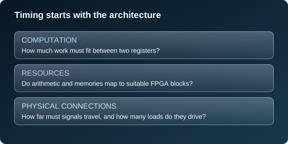
When a design misses timing, it is tempting to try another implementation setting and hope the tool finds a better result. Sometimes a different strategy helps. But the tool is working with the architecture I gave it: the amount of logic in each cycle, the resources selected, and the connections between them.
I treat timing as an early design requirement. The target clock, required throughput, allowed latency, and device resources influence how the system should be divided. Considering these choices early is usually easier than changing interfaces after the design is integrated.
This does not make the tools unimportant. Synthesis and physical optimization are essential. The point is to give them a circuit that can reasonably meet the intended requirements.
Understand what makes a path critical
A register-to-register path launches data from one register, processes it, and delivers it to another. The critical setup path is the one with the least remaining timing margin under the analyzed constraints. It is not necessarily the path containing the most lines of VHDL.
I check the launch and capture clocks, path requirement, slack, cell delay, routing delay, and clock contribution. A short path can look critical if its clock relationship is wrong, so constraints come before optimization.
If logic delay dominates, I examine combinational depth and the operations involved. If routing dominates, I look at fanout, congestion, and physical distance. These problems need different responses. The setup and hold article explains how to read the basic checks.
Reduce combinational depth with deliberate pipelining
A chain of decoding, arithmetic, comparison, and selection may ask one cycle to do too much. Adding a register at a useful boundary can split that work into shorter paths.
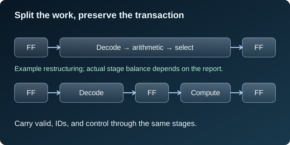
Pipeline balance matters. Splitting a path into one tiny stage and one overloaded stage may achieve little. I use the report and the mapped resource structure to choose useful boundaries.
The added latency is part of the interface. Valid flags, transaction IDs, and control must stay aligned with data. Feedback-dependent calculations may not accept another stage without changing the algorithm or schedule. Pipelining is therefore an architectural decision, not just a register inserted into a failing net.
Fanout can turn a small function into a large physical problem
Fanout is the number of loads driven by a signal. A single enable or mode bit may control registers spread across the device. The logic generating that bit can be simple while its distribution is expensive.
I consider local control, registered control boundaries, or tool-supported driver replication when the report shows that distribution is a bottleneck. Replication must preserve behavior and be checked in the resulting netlist; synthesis may merge equivalent logic.
Using an extra register to distribute control changes its timing unless the related datapath is aligned too. I also avoid treating an ordinary fabric control net as a clock. Dedicated clock resources have their own supported uses and constraints.
Check DSP and block RAM inference
An arithmetic expression in RTL does not automatically guarantee the desired DSP implementation. Operand width, signedness, resets, enables, and pipeline structure can affect mapping. I inspect the synthesis report rather than assuming the multiplication reached a DSP block.
Memories need the same attention. Synchronous read behavior and supported controls help a memory map to block RAM. A requirement to reset every memory location immediately, or an unsupported asynchronous read, can prevent the intended inference and produce a different resource structure.
DSP and BRAM output registers can improve timing where their modes support them. The latency and control behavior must remain correct. Dedicated blocks also occupy particular locations on the chip, so reaching them can introduce routing costs. AMD discusses these tradeoffs in its dedicated-block optimization guidance.
Placement and routing complete the picture
A design can have reasonable logic depth and still struggle because connected blocks are far apart or routing is congested. Wide buses and heavily shared resources create physical demands that are not obvious from the RTL alone.
I inspect the failing paths and congestion before imposing a floorplan. Thoughtful placement constraints can help a clear physical problem; overly tight constraints can remove the tool’s flexibility and make another problem worse.
Early synthesis and implementation runs expose these issues while the architecture can still change. I then recheck final routed setup, hold, and applicable timing corners. A good synthesis estimate is useful guidance, not final sign-off.
Use the report to choose the next change
- Confirm the clocks, I/O requirements, and justified exceptions.
- Identify the worst paths and any repeated failing structure.
- Separate logic depth, resource timing, fanout, and routing concerns.
- Make one focused architectural or implementation change.
- Verify functional behavior, including any changed latency.
- Reimplement and compare the routed results.
I do not add false-path or multicycle exceptions simply to hide violations. They must describe real operating behavior, including the associated hold implications. Likewise, a deeper pipeline is not a general repair for a hold violation.
The strongest starting point is an architecture designed around realistic cycle budgets. Tool tuning then works with that structure. AMD’s pipelining guidance and timing-report guide provide further detail.