A pass is evidence with a defined scope
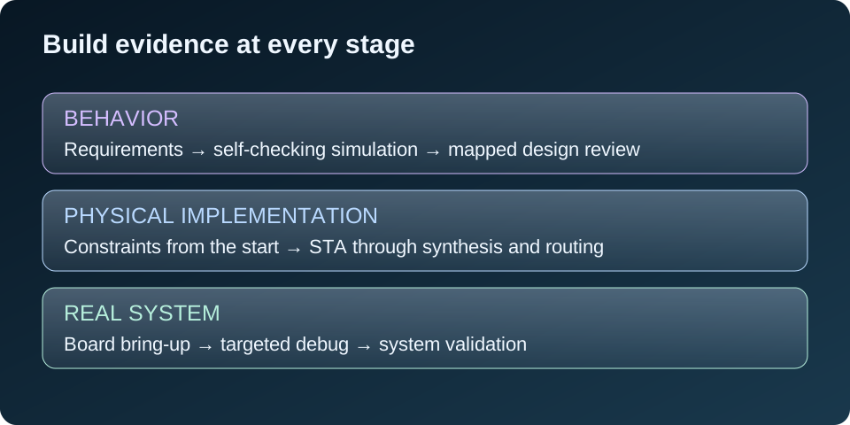
A passing testbench is an important result. It tells me that the exercised behavior matched the checks. It does not automatically prove the mapped circuit, its timing constraints, or the complete board-level system.
I build verification evidence in layers: simulation, synthesis review, constraints, static timing analysis, implementation, hardware bring-up, targeted debug, and system validation.
This is a roadmap, rather than a strict one-way sequence. Constraints belong at the beginning, timing is reviewed throughout implementation, and a hardware discovery often sends me back to simulation. My earlier simulation-to-hardware article introduces the distinction; here I focus on the evidence needed at each stage.
1. Check behavior against the requirements
I start with a written description of what the block must do. The testbench should compare actual outputs with expected results, exercise important boundaries, and fail if the expected response never arrives.
Reset, overflow, empty/full transitions, backpressure, and interrupted activity often reveal assumptions that normal traffic misses. A simulation ending without assertions is not necessarily a correctness check.
Ordinary RTL simulation uses digital models. It does not establish analog metastability reliability or cable signal quality. CDC, reset-domain crossings, and external interfaces need additional review. See the self-checking testbench article for a small example.
2. Inspect what synthesis created
Synthesis maps the RTL into FPGA resources. I check warnings, inferred memories, DSP use, latch inference, removed logic, and utilization. A design that synthesizes successfully may still map differently from the intended architecture.
An inferred memory becoming a large register-and-mux structure can change area and timing. Logic unexpectedly optimized away can reveal an unconnected signal or a constant condition. These findings should be understood rather than accepted simply because the tool finished.
3. Make the timing contract accurate
I define primary and generated clocks, external I/O timing where applicable, and justified timing exceptions. The constraints must describe the operating system, not the result I hope to see in a report.
Static timing analysis, or STA, uses the implementation’s delay models and these constraints to check timing requirements. I review setup, hold, pulse-width requirements, clock relationships, and unconstrained paths as applicable.
A positive worst setup slack does not cover a missing constraint, an unsafe CDC protocol, or a functional error. Exceptions such as false paths and multicycle paths require a real design justification.
4. Recheck the placed and routed design
Implementation places resources and routes their connections. Routing can change the timing picture significantly, so synthesis estimates are an early indicator rather than final sign-off.
I review final routed timing, design-rule checks, CDC/reset-domain findings, important warnings, and resource use. The target device, tool version, source revision, and constraints should be recorded with the result.
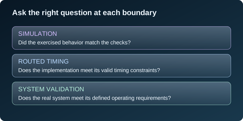
Bitstream generation means that a programming file was produced. It does not by itself mean timing is clean or that hardware testing has passed. AMD’s timing-path documentation explains the physical path information behind timing analysis.
5. Bring up the board in small steps
Before connecting equipment, I check the board revision, target part, pins, I/O standards, voltage compatibility, and power/boot configuration. Then I confirm programming, clocks, reset, and a small known behavior before exercising the full application.
A simple activity indication can help locate a problem, but an LED alone does not prove correct frequency or system behavior. I test the actual interface with known inputs and compare the observed result with an explicit expectation.
For an HDMI project, I would check display compatibility and image timing. For an audio project, I would also check codec setup, sample clocks, and known input signals. These are planned checks unless their results have actually been recorded.
6. Use ILA to answer a specific question
An Integrated Logic Analyzer captures selected internal digital signals. I choose probes and a trigger around a question: did the request arrive, did the FIFO overflow, or did the state machine stop advancing?
The sampling clock must suit the signals being observed. Probing unrelated clock domains does not make their signals synchronous or reveal analog metastability. A scope or other appropriate instrument is still needed for electrical measurements.
ILA consumes resources and can affect placement and timing. I reimplement and recheck the instrumented build. Debug visibility is something I plan where useful; it is not a mandatory extra step when the required behavior is already observable. AMD’s programming and debug guide describes the supported flow.
7. Validate the complete system and preserve the evidence
System validation checks the agreed requirements with real software, interfaces, and equipment. I include sustained traffic, boundary conditions, error recovery, repeated startup, and the operating conditions relevant to the product.
I separate the functional result from performance measurements. Latency, throughput, and accuracy claims need defined measurement points and recorded data. A visible output is useful evidence, but it is not automatically a calibrated measurement.
When a hardware failure is understood, I try to make a repeatable regression test for it. I keep the source revision, bitstream identity, configuration, logs, and limitations together. The final status should say what passed and what remains untested, so the next engineer can assess the result without guessing.